Explore


Sharpen Up!
Sign up for our free newsletter and start your day with in-depth reporting on the latest topics in education.
The Latest
-
skills for the future
极速赛车官方-168极速赛车开奖记录查询结果-英国赛车一分钟计划-Reinventing Report Cards: Reading, Writing, Collaboration and Other Work Skills
-
North Carolina
National Conference Convenes Education Leaders Around ‘Future-Focused Schools’
-
opinion
‘Brown’ Devastated the Black Teaching Force. It’s Long Past Time to Fix That
-
Maryland
Maryland May Join Other States to Retain Third Graders With Low Reading Proficiency
-
Indiana
Indiana’s Ed Scholarship Accounts See Boosted Participation Ahead Of 2024-25 Term
-
Oklahoma
Oklahoma’s Largest School Districts Now Led by Black Women, Making State History
-
Analysis
Building Bridges Across State Lines Is Set to Transform Education in Connecticut
-
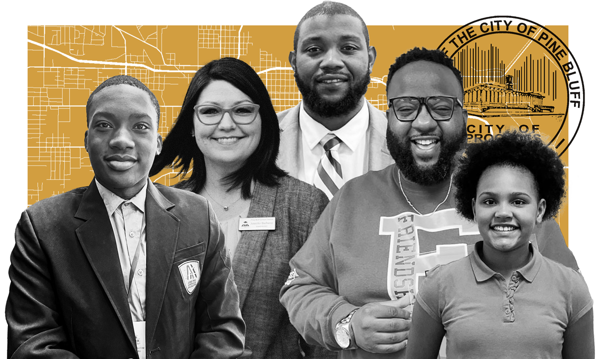
Ohio
Private School Just For Low Income Kids Looks To Create Thriving Adults
-
opinion
High-Poverty Schools in Colorado, Massachusetts Defying the Odds for Students
-
microschools
The Rise Of Education Entrepreneurs In Minnesota
-
Chronic Absenteeism
With Poll Showing 1 in 4 Kids Is Chronically Absent, How 1 District Is Reaching Out
-
California
California Teachers are Using AI to Grade Papers. Who’s Grading the AI?
-
Indiana
Indiana’s Overall Child Well-Being Scores Decline in New National Report
-
alabama
Alabama Lawmakers Consider New School Funding Model
-
alabama
AI in Medicine Graduate Program Approved at University of Alabama at Birmingham
-
Wyoming
Wyoming Advocates Want More Parents to Have Access to Education Savings Accounts
-
New Mexico
New Mexico Ranks 50th in Child Welfare, Shows Mixed Progress in Several Areas
-
Independence Day
The Declaration of Independence Wasn’t Really Complaining about King George
-
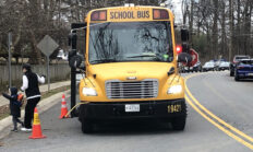
News
Drivers Keep Passing Stopped School Buses, Despite Use Of Cameras To Catch Them
-
opinion
Most Philly Students Have College Ambitions, But Prep Varies by High School
-
Kansas
Kansas Public Schools Relying on Blueprint for Literacy to Build Reading Skills
-
opinion
New Database Features 250 AI Tools That Can Enhance Social Science Research
-
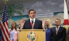
Florida
Public School Chaplains, Other Education Laws Take Effect Monday in Florida
-
Alaska
Alaska Supreme Court Reverses Homeschool Allotment Ruling
-
mississippi
New Mississippi Law Makes ASL a Foreign Language Credit
-
Oregon
Oregon Proposes New Literacy Requirements For Teacher Training and Licensing
-
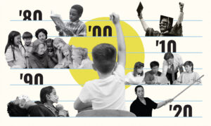
Analysis
When Was the Golden Age of American K-12 Education? And How Can We Tell?
-
Wisconsin
Wisconsin School Violated Seclusion and Restraint Policies, Investigation Finds
-
EDlection 2024
Amid Disastrous Debate, a Lost Opportunity to Address Children’s Issues
-
Illinois
Illinois Governor Signs Bill Creating New Department of Early Childhood


极速一分钟赛车彩票1分钟官网开奖结果 Trending Now


Children deserve a first-rate education.
The public deserves first-rate reporting on it.
Please make a tax-exempt donation to 一分钟赛车开奖记录查询下载-赛车数据分析记录 The 74.
School (In)Security


1分钟极速赛车正规官方视频直播 Opinion

2024直播赛车168开奖结果视频 开奖历史记录一览 Video


2024极速赛车开奖结果-极速赛车1分钟开奖计划app下载 Special Series
1分钟极速赛车开奖官网记录 The 74 Interview
168极速赛车全国开奖记录直播 The 74 interviews the top thinkers, policymakers and leaders in American education
- Rhode Island Ed Chief Infante-Green on Charter Schools, Enrollment Loss and Providence’s Future
- Why Many ‘High-Achieving’ Students Don’t Become Teachers and What We Can Do About It
- Why Play Is Essential For Children: Psychologist Peter Gray Sounds the Alarm About Excessive Adult Oversight & What It’s Doing to Kids’ Mental Health


More Stories

Invest in independent journalism
Donate now to 168极速赛车官网 The 74


New Mexico